
Generator Room and Installation
Generator room ventilation and installation guide: radiator air discharge, exhaust line and back pressure, fuel, concrete plinth, vibration and earthing.
Contents
A proper generator installation rests on four foundations: adequate ventilation with the radiator’s hot air discharged outside, an exhaust line of suitable diameter and routing, a solid, vibration-isolating foundation, and safe fuel and earthing installations. Exact dimensions are taken from the engine and set data sheets; the design should be carried out by a qualified engineer in accordance with local regulations.
How are generator room dimensions determined?
There is no single standard size for a generator room; the room dimensions are worked out from the selected set and its installation requirements:
- Set dimensions: The starting point is the length × width × height of the open-type set. Per-model dimensions are given on the product pages and in the data sheet.
- Service clearance: Space is left on every side of the set for maintenance and ventilation. For example, the Cummins installation guide recommends at least 3 ft (about 0.9 m) around the set; some facility specifications require 1.2 m. The exact value is taken from the installation drawing of the selected model and the project design.
- Radiator and air duct: Additional space is needed for the radiator discharge duct and for the air inlet and outlet openings.
- Height: Clearance above the set is planned for the exhaust line, silencer and cable trays.
- Access route and auxiliary equipment: The door or removal opening must be wider than the set, and space is also needed for the day tank, transfer switch (ATS) and batteries.
For model dimensions by power rating, see the power pages on our products page.
1. Ventilation and cooling
A running diesel generator both needs air for combustion and produces a significant amount of heat. Room ventilation must meet three needs:
- Combustion air: The air the engine needs to run.
- Radiator cooling air: The air drawn by the radiator fan, usually the largest item.
- Removal of room heat: Heat radiated into the room from the engine block, alternator and exhaust pipe.
These values are given in the data sheets in m³/min. Points to watch in practice:
- The fresh air inlet should be on the alternator side of the set and the hot air outlet on the radiator side; this way the air flows along the set.
- The radiator’s hot air should be discharged directly outside through a duct connected to the radiator face with a flexible connection. Otherwise hot air recirculates in the room and the set overheats.
- Because of louvre and attenuator losses, the inlet opening is made larger than the radiator face; a common practice is to plan a net inlet area of approximately 1.5 times the radiator face.
- The total air resistance of louvres, attenuators and ducts must not exceed the permissible external resistance of the radiator fan.
- To prevent hot air being drawn back in through the inlet, the inlet and outlet should be placed on different façades or at a sufficient distance apart.
2. Exhaust line and back pressure
The exhaust system is critical for both safety and engine performance:
- A flexible connection (compensator) is fitted at the engine outlet so that vibration and thermal expansion are not transmitted to the pipework.
- The weight of the pipe is carried by hangers and supports, not by the engine.
- The line should be as short as possible with few bends. Every bend and every metre of pipe increases back pressure.
- Back pressure must not exceed the limit stated in the engine manufacturer’s data sheet. Excessive back pressure leads to loss of power, increased fuel consumption and high exhaust temperature. Pipe diameter is selected by calculating length and silencer losses.
- The exhaust pipe and silencer inside the room are covered with thermal insulation.
- A condensate drain is fitted at the lowest point of the line, and a rain cap or suitable termination at the outlet end.
- The exhaust outlet should be away from windows, ventilation inlets and areas where people are present, at a point where gases will not return into the building.
- At wall and floor penetrations, a suitable clearance or insulation is left from combustible materials.
3. Fuel system
- The day tank and the supply and return lines are designed according to the engine manufacturer’s suction height and pressure limits.
- A bund (spill containment) or double-walled tank is used to guard against leaks.
- Fuel lines include flexible connections, valves and filters; avoiding copper is a common recommendation.
- The tank vent is routed outside; the filling point is kept accessible.
- Depending on the amount of fuel stored, fire regulations may impose additional requirements.
4. Floor, plinth and vibration
- The set is placed on a flat and level reinforced concrete plinth. The plinth size and reinforcement are determined by a structural design taking into account the set’s weight, the bearing capacity of the ground and operating loads.
- The engine and alternator are mounted on anti-vibration mounts on the set’s base frame. If necessary, additional isolators are fitted between the base frame and the plinth.
- The plinth can be separated from the building structure; this reduces structure-borne noise and vibration transmission.
- Sufficient clearance is left around the set for maintenance; access is planned for alternator removal and radiator cleaning.
5. Electrical connection and earthing
- Power cables are sized according to current-carrying capacity and voltage drop; a flexible connection is made to the set.
- Neutral and protective earthing are designed to be compatible with the site’s earthing system. Earth resistance is measured and documented.
- Changeover between the mains and the generator is made through a transfer panel (ATS) that prevents backfeed.
- If several sets are to run in parallel, synchronization and load sharing are designed separately.
6. Safety and regulations
Requirements vary with the installation site, power rating and building type. In Türkiye, the following topics in particular should be checked at the design stage:
- Provisions of the regulation on fire protection of buildings (fire resistance of the generator room, doors, fuel storage)
- Regulations on internal electrical installations and earthing
- Municipal zoning and environmental noise legislation
- Occupational health and safety requirements
This article is for general information; for exact requirements, the legislation in force and the competent authorities should be consulted.
Pre-installation checklist
- Have the airflows, exhaust flow and permissible back pressure been taken from the data sheet?
- Is the radiator’s hot air ducted outside?
- Has the back pressure of the exhaust line been calculated?
- Has the plinth been structurally designed?
- Are earthing and the ATS connection defined in the design?
Next step
Where a room cannot be built, an outdoor-rated generator canopy is a practical solution. See our ATS transfer panel page for automatic changeover and our synchronization panel page for parallel operation. For project-specific data sheets and installation information, contact us.
Planning a generator for a project?
Send us the power, voltage and destination. We reply with a suitable model, the factory price and the lead time within 24 hours on working days.
Frequently asked questions
How is generator room ventilation calculated?
The required airflow consists of the engine's combustion air, the radiator cooling air and the heat that must be removed from the room. These values are given in the engine and set data sheets in m³/min. The air inlet opening is made larger than the outlet opening, and the radiator's hot air is discharged directly outside through a duct.
How should a generator exhaust pipe be installed?
The exhaust line should be connected to the engine with a flexible connection (compensator), its weight carried by hangers rather than the engine, kept as short as possible with few bends, insulated and fitted with a drain point for condensate. Total back pressure must not exceed the value permitted by the engine manufacturer.
What permits are required for a generator installation?
The permits required vary with the installation site, power rating, amount of fuel stored and the building's use. In Türkiye, regulations on fire protection, electrical installations and earthing, as well as municipal and environmental legislation, should be checked at the design stage, and the installation should be designed by a qualified engineer.
Featured models
Technical data of models in frequently requested power ratings:
- 38 kVATRX QZ TA 0038Quartz Q490ZD
- 58 kVATRX QZ TA 0058Quartz Q4105D
- 77 kVATRX QZ TA 0077Quartz Q4105ZD
- 105 kVATRX QZ TA 0105Quartz Q4105AZLD
- 155 kVATRX QZ TA 0155Quartz Q6105AZLD
- 260 kVATRX SD TA 0260SDEC SC9D310D2
- 300 kVATRX SD TA 0300SDEC SC9D340D2
- 400 kVATRX SD TA 0400SDEC SC15G500D2
- 520 kVATRX SD TA 0520SDEC SC25G610D2
Related articles
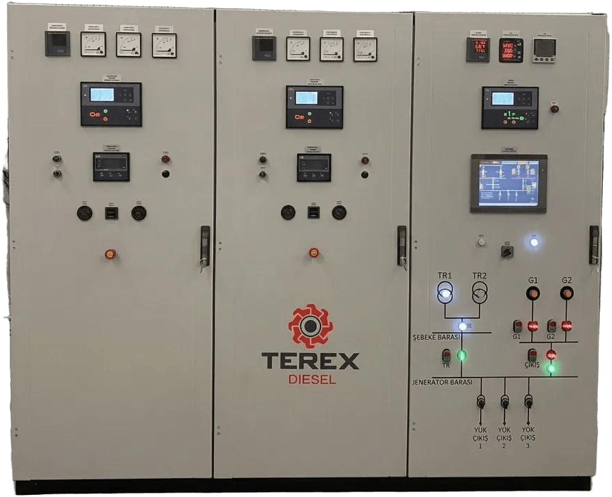
What Is an ATS? Automatic Transfer Switch
What is an ATS and how does it work? Transfer sequence, delay times, 3- or 4-pole choice, current calculation (kVA × 1.44) and a checklist.
Using a UPS with a Generator
For a 200 kVA UPS with an IGBT rectifier, plan about 250–300 kVA of generator; an older 6-pulse UPS may need twice that. Harmonics and frequency.
Generator Earthing (Grounding)
How is a generator earthed? Protective and system earthing, TN and TT systems, the neutral–earth link, ATS pole count and resistance measurement.
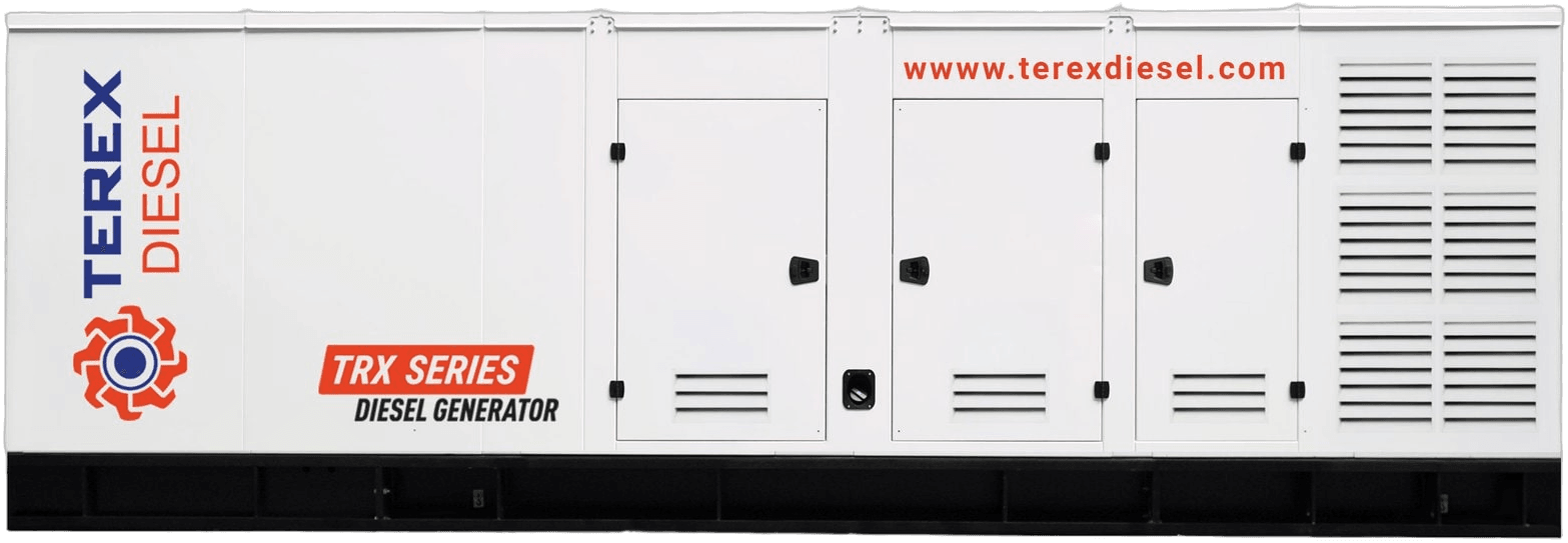
Paralleling (Synchronising) Generators
Generator synchronization (paralleling): sync conditions, kW and kVAr load sharing, N+1 redundancy, grid paralleling and a comparison with a single set.
Remote Generator Monitoring
How does generator remote monitoring work? Controller, GSM/4G, Ethernet, Modbus, what values to monitor, alarm settings and cyber security.
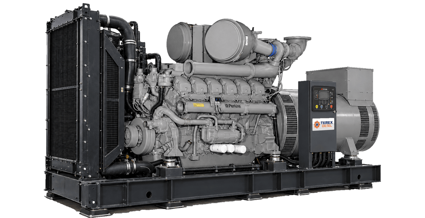
Generator Exhaust Systems: Piping, Silencers and Back Pressure
How to design a generator exhaust line: pipe diameter, bends and length, back pressure limit, silencer grades, flexible connector, insulation and outlet.