
What Is an ATS? Automatic Transfer Switch
What is an ATS and how does it work? Transfer sequence, delay times, 3- or 4-pole choice, current calculation (kVA × 1.44) and a checklist.
Contents
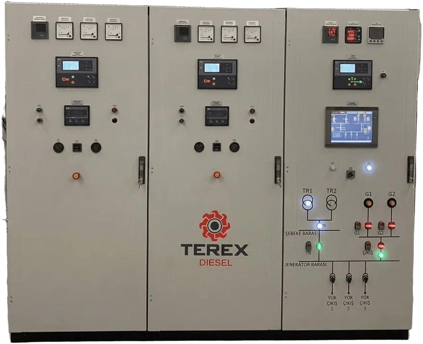
When the mains fails, the ATS (Automatic Transfer Switch) panel starts the generator automatically and transfers the load to it. The generator starts a few seconds after the outage; the load is typically transferred to the generator within 10–15 seconds. When the mains returns, the load is transferred back to the mains and the generator stops automatically after a cool-down run of a few minutes.
Most problems seen on site with ATS panels come from the wrong number of poles, delay times set to zero, or panels that were not tested during commissioning.
What is inside an ATS panel?
- Switching device: A contactor, motorised circuit breaker or motorised changeover switch. It connects the load to either the mains or the generator.
- Control unit: Monitors mains voltage, frequency and phase sequence. Manages the delays. Sends the “start” and “stop” commands to the generator.
- Mechanical and electrical interlocking: The mains and the generator can never be connected to the load at the same time. The safety of the system depends on this.
- Metering and alarms: Voltage, current, status information. Many models also offer remote monitoring.
The international reference for transfer switching equipment is IEC 60947-6-1. The utilisation category of the switching device must suit the type of load. In a facility with heavy motor loads, this detail matters.
How does the transfer proceed? Timings
| Step | What happens? | Typical setting (approximate) |
|---|---|---|
| 1. Outage detection | The mains fails or goes out of limits | 1–5 s delay |
| 2. Engine start | Start command goes to the generator | A few seconds |
| 3. Steady state | Voltage and frequency settle | A few seconds |
| 4. Transfer | Load moves to the generator | Total usually ~10–15 s |
| 5. Mains return | Mains stability is monitored | Usually a few minutes |
| 6. Retransfer | Load returns to the mains | — |
| 7. Cool-down | Generator runs off-load and stops | Usually 3–5 min |
The values are examples. Actual settings are made according to the facility, the generator control panel and the relevant regulations.
Remember two things. First: during those 10–15 seconds the load has no power. Servers, medical equipment or PLCs cannot tolerate that gap; for them, UPS and generator together is the answer. Second: the waiting time on mains return is there for a reason. Handing the load straight back while the mains is dropping in and out a few times hits motors and equipment with shock after shock.
Types of transfer
- Open transition (break-before-make): One source opens first, then the other closes. This is the most common solution. There is a short interruption during the transfer.
- Delayed transition (centre-off): The switch waits briefly in the “0” position. On large pump and fan motors this gives the residual voltage time to decay and reduces the inrush current.
- Closed transition (make-before-break): On mains return, the two sources run in parallel for a very short time and the load is transferred without interruption. It needs synchronization and additional protection. Paralleling with the grid may require permission from the distribution company. Details are in our article on synchronized (parallel) operation.
How do you choose the right ATS?
1. Current. In a 400 V three-phase system:
I (A) = kVA × 1,000 ÷ (√3 × 400) ≈ kVA × 1.44
| Generator | Rated current (approximate) | Typical ATS rating |
|---|---|---|
| 50 kVA | 72 A | 80–100 A |
| 100 kVA | 144 A | 160 A |
| 250 kVA | 361 A | 400 A |
| 500 kVA | 722 A | 800 A |
| 1,000 kVA | 1,443 A | 1,600 A |
Select the next standard rating above the calculated current. Cables and protective devices must also be matched to the same current.
2. Number of poles. 3-pole or 4-pole? The answer lies in the facility’s earthing system. Systems in which the generator neutral is earthed separately usually need a 4-pole ATS. We cover this in our article on generator earthing.
3. Short-circuit withstand. The ATS must suit the short-circuit current at its connection point and the upstream protective device.
4. Control compatibility. The control unit must be able to talk to the generator panel. Delays, test mode and alarm outputs must be adjustable.
5. Scope. The whole building, or only critical loads? Grouping critical loads on a separate panel often solves the job with a smaller generator and ATS. You can estimate the requirement with the power calculator.
Common mistakes on site
- The number of poles is chosen without regard to earthing. Result: residual current devices trip for no apparent reason when the load moves to the generator.
- The outage detection delay is set to zero. The generator starts on even a dip of a few hundred milliseconds in the mains. Dozens of unnecessary starts a day.
- The cool-down time is shortened. The turbo and engine stop while hot. A habit that eats into service life.
- Phase sequence is not checked. On transfer to the generator, a pump runs backwards. Usually noticed at the first real outage.
- The ATS is never tested. The generator is run every month, but off-load. The transfer is tried for the first time in a real outage, and sometimes it fails.
Checklist
- Has the rated current been calculated and the next standard ATS rating up selected?
- Are the earthing system and the 3/4-pole decision defined in the design?
- Are short-circuit withstand and the upstream protective device compatible?
- Is there mechanical and electrical interlocking?
- Have the delays (detection, return, cool-down) been set?
- Has the phase sequence been checked?
- Has communication with the generator control panel been tested?
- Is a periodic transfer test included in the maintenance plan?
Periodic testing
Only a real transfer shows that the ATS works. During scheduled maintenance the generator should be run on load, transfer and retransfer should be tried, and delays and alarms checked. If possible, a real outage should be simulated by opening the mains breaker. For the scope of maintenance, see our scheduled maintenance page.
Next step
The Terex Diesel team helps you choose the ATS panel to suit the generator rating and your facility. For product information, see our ATS transfer panel page; for your project, contact us.
Planning a generator for a project?
Send us the power, voltage and destination. We reply with a suitable model, the factory price and the lead time within 24 hours on working days.
ATS connection diagram
- Mains fails, or voltage/frequency goes out of limits.
- The ATS waits a few seconds (to ride through brief dips), then sends a start signal to the generator.
- Once the generator reaches voltage and frequency, the ATS transfers the load; typically 10–15 seconds in total.
- When mains returns, the ATS confirms it is stable, transfers the load back, and the generator stops after a cool-down run.
Frequently asked questions
How many seconds after a power cut does the ATS switch to the generator?
It depends on the settings. In a typical diesel backup power system, the outage detection delay, starting the engine, letting voltage and frequency stabilise and the transfer itself are usually completed together in around 10–15 seconds. In critical facilities such as hospitals, the maximum permitted time is set by the relevant standards and regulations.
Should an ATS be 3-pole or 4-pole?
The decision depends on the facility's earthing system. A 4-pole ATS is used in systems where the generator neutral is earthed separately and the neutral must also be switched. In some systems where the neutral is earthed at a single point, a 3-pole ATS may be sufficient. The choice should be made by the engineer preparing the electrical design.
How is the ATS current calculated?
In a 400 V three-phase system, the generator's rated current is approximately kVA × 1.44. For example, a 250 kVA generator draws about 361 A, so the next standard rating up, a 400 A ATS, is selected. Cables, fuses and short-circuit withstand must also be checked separately.
Featured models
Technical data of models in frequently requested power ratings:
- 38 kVATRX QZ TA 0038Quartz Q490ZD
- 58 kVATRX QZ TA 0058Quartz Q4105D
- 77 kVATRX QZ TA 0077Quartz Q4105ZD
- 105 kVATRX QZ TA 0105Quartz Q4105AZLD
- 155 kVATRX QZ TA 0155Quartz Q6105AZLD
- 260 kVATRX SD TA 0260SDEC SC9D310D2
- 300 kVATRX SD TA 0300SDEC SC9D340D2
- 400 kVATRX SD TA 0400SDEC SC15G500D2
- 520 kVATRX SD TA 0520SDEC SC25G610D2
Related articles
Generator Room and Installation
Generator room ventilation and installation guide: radiator air discharge, exhaust line and back pressure, fuel, concrete plinth, vibration and earthing.
Using a UPS with a Generator
For a 200 kVA UPS with an IGBT rectifier, plan about 250–300 kVA of generator; an older 6-pulse UPS may need twice that. Harmonics and frequency.
Generator Earthing (Grounding)
How is a generator earthed? Protective and system earthing, TN and TT systems, the neutral–earth link, ATS pole count and resistance measurement.
Paralleling (Synchronising) Generators
Generator synchronization (paralleling): sync conditions, kW and kVAr load sharing, N+1 redundancy, grid paralleling and a comparison with a single set.
Remote Generator Monitoring
How does generator remote monitoring work? Controller, GSM/4G, Ethernet, Modbus, what values to monitor, alarm settings and cyber security.
Generator Exhaust Systems: Piping, Silencers and Back Pressure
How to design a generator exhaust line: pipe diameter, bends and length, back pressure limit, silencer grades, flexible connector, insulation and outlet.